3.5 Mm Jack to Xlr Wiring Diagram autocardesign
The wiring diagram Xlr to Jack connection consists of two components: the Xlr connector and the Jack connector. The Xlr connector is a 3-pin connector that is used to connect a microphone or other audio equipment to an amplifier or mixer. The Jack connector is a 2-pin connector that is used to connect the amplifier or mixer to a speaker.
[11+] Cpu Wiring Diagram Xlr To 14, Balanced Line Output From MiniDSP 2x4HD (help!) Audio
XLR diagrams display the wiring configuration for an XLR connection, which is a type of electrical connector commonly used in audio systems. The diagrams illustrate how the various wires in the connection are connected to each other. Each diagram consists of several lines and symbols that represent the wiring layout.
Xlr Wire Diagram Wiring Diagram Xlr Wiring Diagram Wiring Diagram
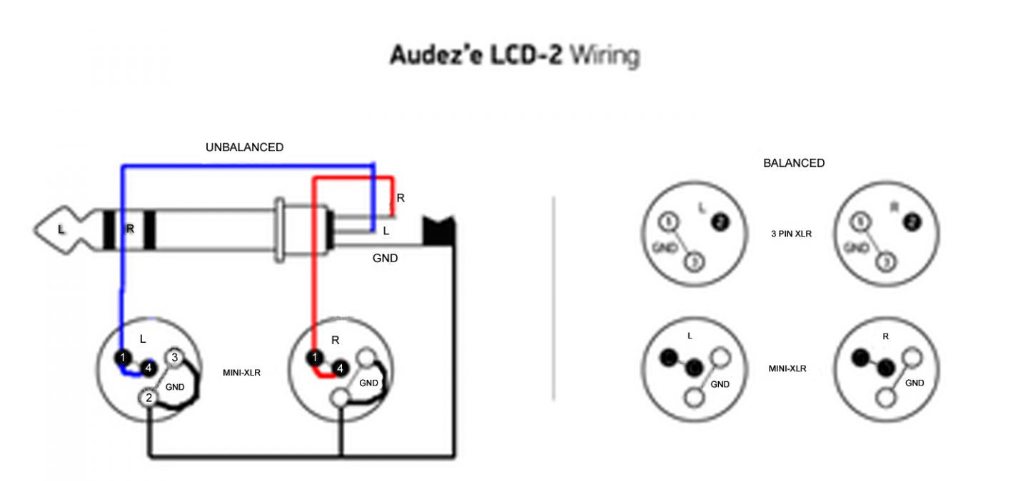
The Mini XLR wiring diagram is a visual representation of the connections made within a Mini XLR connector, which is commonly used in professional audio equipment. The Mini XLR connector, also known as a TA3 connector, is a compact version of the XLR connector and is often used in applications where space is limited.

Xlr Male To Female Wiring Diagram GMC Forum > Software Audio Production Blog Male to female
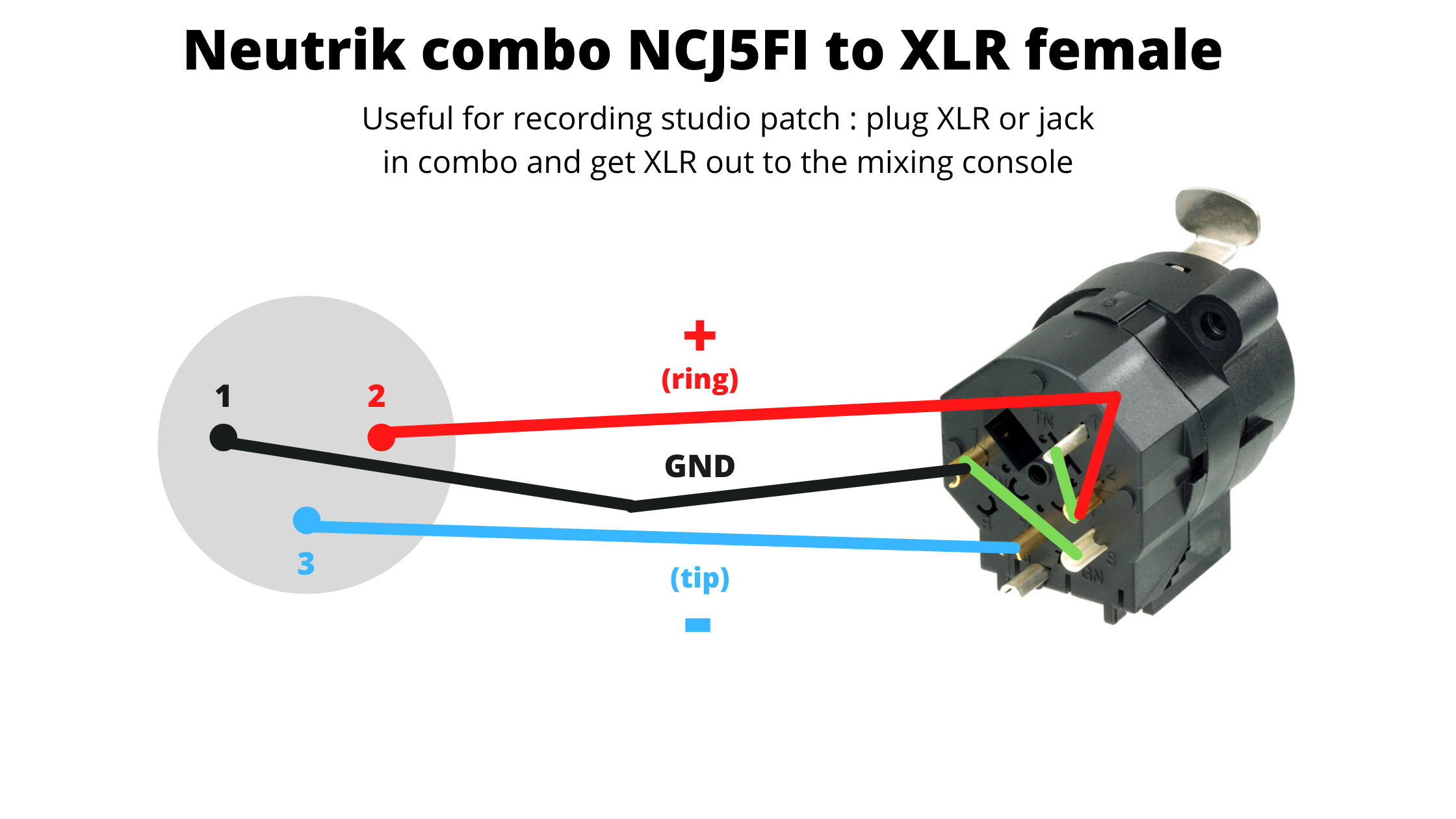
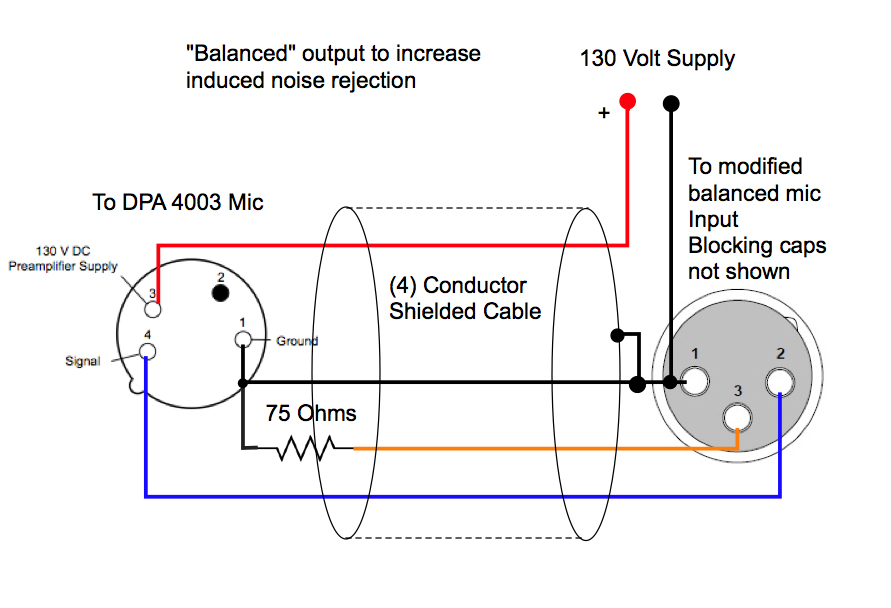
Steve Swinden. SOS Technical Editor Hugh Robjohns replies : The AES specifications do say that you should wire each pin‑1 to the shell, and there's good sense behind that policy, but only if all of the equipment being connected together is built and wired correctly too. A small capacitor wired between XLR pin‑1 and the shell maintains.
Soldering Xlr Cable Wiring
Wire Colors and Codes When it comes to wiring diagrams for XLR connectors, it is important to understand the different colors and codes that are associated with each wire. Most of the wires are color-coded, so that they can easily be identified and connected properly. The most common colors are red, black, white, green, blue, and yellow.
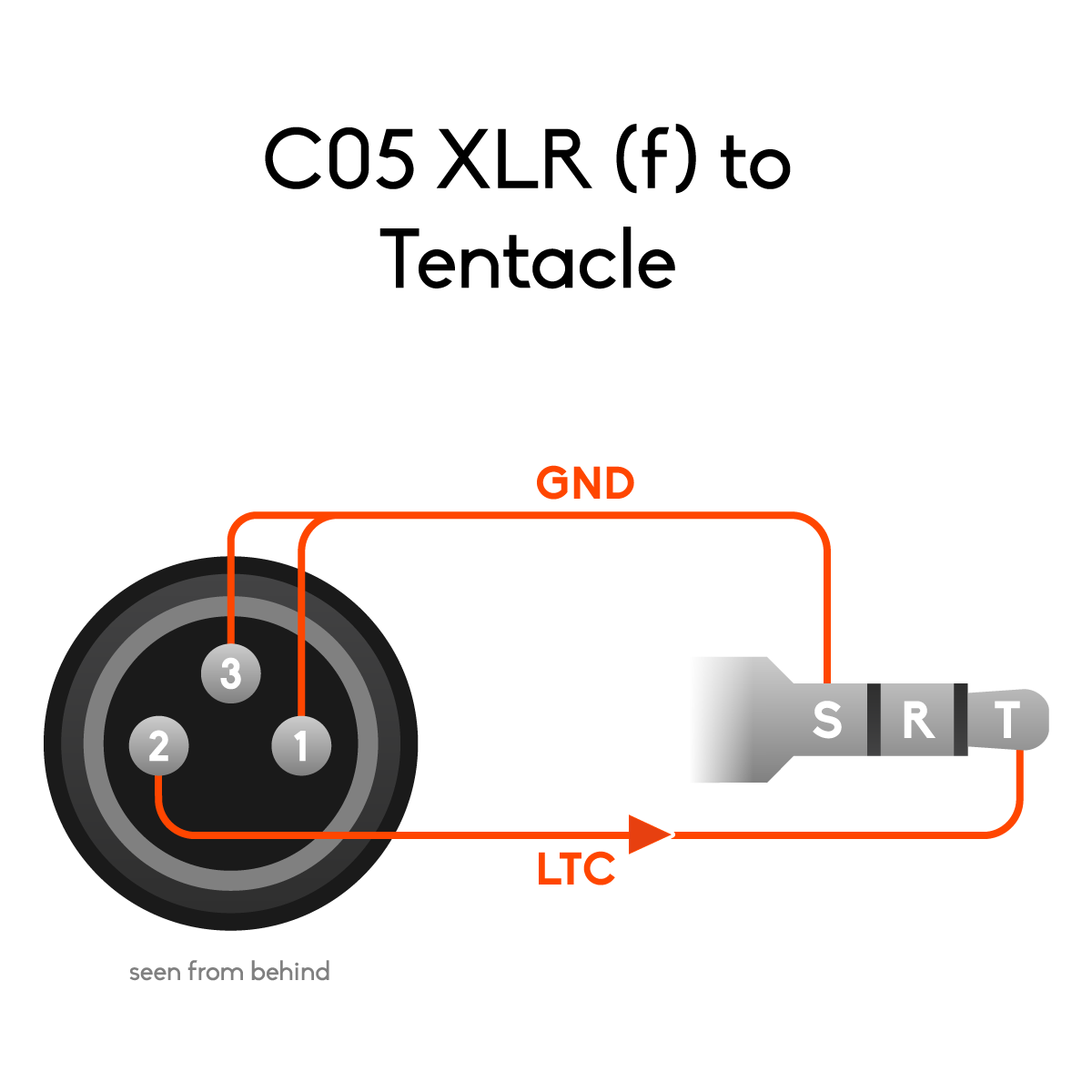
Pinouts and wiring diagrams for Tentacle cables Tentacle Sync
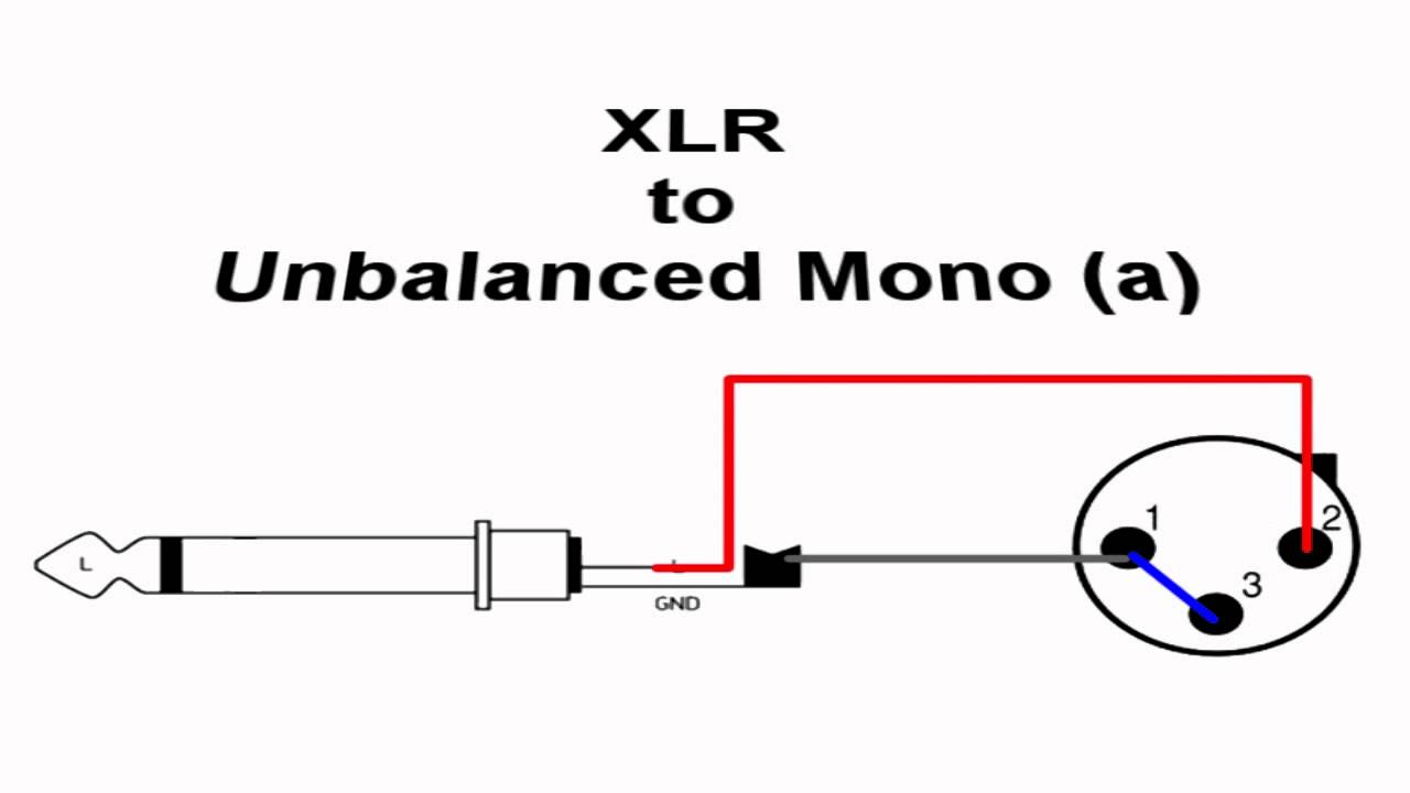
A wiring diagram is an essential tool for connecting audio equipment together. It displays the physical connections between the components, as well as the signal flow between them. With the right wiring diagram, you can easily connect any type of XLR cable to a mono jack, allowing you to plug in microphones, mixers, and other audio devices.
Wiring Diagram For Xlr Wiring Diagram Schemas
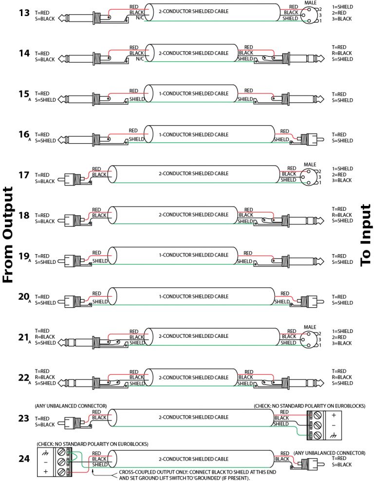
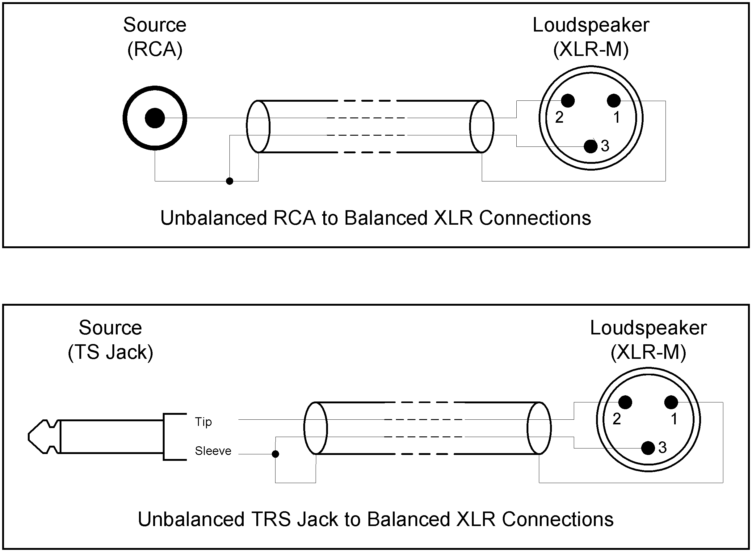
The XLR connector can support both balanced and unbalanced connections, and it is important to understand the wiring diagram for each type of connection. In an unbalanced XLR connection, there are typically three pins: pin 1 is the ground, pin 2 is the positive signal, and pin 3 is the negative signal.
How To Build Your Own Xlr Cables A Stepstep Guide Studio Diy Xlr Wiring Diagram Cadician
Design XLR connectors are available in male and female versions in both cable and chassis mounting designs, a total of four styles. This is slightly unusual as many other connector designs omit one of the styles (typically a chassis mounting male connector).
Xlr Wiring Diagram Pdf Wiring Diagram
Third Hand Tool Lighter Materials Cable (I recommend Mogami, Belden, or Canare) Solder Neutrik XLR connectors (models NC3MXX, NC3FXX (silver) or NC3MXX-BAG, NC3FXX-BAG (black)) Heat Shrink Building the XLR Cables Step 1: Measure and Cut the Proper Length of Cable
Xlr To Trrs Wiring Diagram First Wiring
Step 1: Strip the ends of a cable using the wire cutters. Take off half an inch or 2cm of rubber insulation from the outside. Step 2: You'll see the thin wires. They form the internal insulation. Grab them all and twist them aside. So you get enough room to take the cloth insulation. Step 3: Strip the black and white wire.

Xlr Wiring Diagram Cadician's Blog
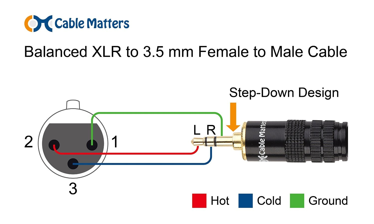
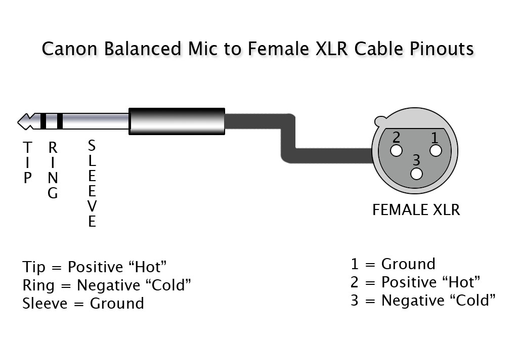
The hot wire is connected to pin 2, and the cold wire is connected to pin 3. It is important to note that the XLR cable wiring diagram may vary depending on the specific application and equipment. Some XLR cables also include additional pins for features like phantom power, which is commonly used to power condenser microphones.
Wiring diagram XLR connector Phone connector Electrical Wires & Cable, frieze, angle, rectangle
Cut the cable. Strip off the jacket. Unwind the braid (if there is one). If it's a foil shielded cable, just cut off the foil and use the bare drain wire. Cut the two insulated wires inside to the appropriate dimensions. Strip the two insulated wires to reveal 1/8th of an inch (3mm) of bare conductor on each. Tin those wire.
Xlr Wiring Diagram Pdf Cadician's Blog
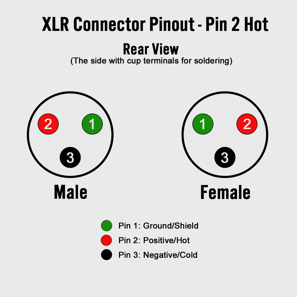
XLR cables are primarily used for professional audio, video, and stage lighting equipment. The most common XLR cable is terminated with 3-Pin XLR connectors. While there are various configurations, or "pinouts", used in wiring 3-Pin XLR cables, the AES industry standard for balanced audio XLR wiring is what is referred to as Pin 2 Hot.

stereo xlr wiring diagram
How to wire an XLR

Wiring Diagram For Xlr Wiring Diagram Schemas
Shop Cable 3-Pin XLR Audio Pinout Three-pin XLR connectors are by far the most common style, and are an industry standard for balanced audio signals. The pinout listed below is the Audio Engineering Society (AES) industry standard for balanced audio XLR wiring. Sony 4-Pin XLR D.C. Power Supply Pinout 5-Pin XLR DMX Cable
Xlr To Microphone Plug Wiring Diagram / Wiring Diagram For Xlr schematic and wiring diagram
XLR connectors are part of almost every aspect of profes-sional audio; as a microphone connector, in lighting sys-tems, and found in almost any piece of sound equipment. • Accommodates wire size AWG 24 - 22 or 0.22 - 0.34 mm2 • Absolute leadfree and solderless connection: - RoHs compliant - health and eco-friendly
